Sw Tachometer Wiring Diagram
Wiring Diagrams
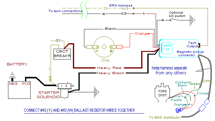
Msd Installation

Ng 2616 Peterbilt Tachometer Wiring Diagram Free Diagram
Https Www Stewartwarner Com Wp Content Uploads 2018 12 120300 Traditional Electric Tachometer Pdf

35 Rpm Gauge Wiring Diagram Wiring Diagram List

Stewart Warner Stewart Warner Heavy Duty Electrical Battery
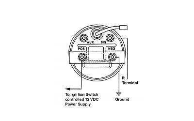
To wire the magnetic sensor pickup use 18 awg 1 0mm twisted pair shielded cable.
Sw tachometer wiring diagram. This tachometer is factory calibrated for 8 cylinder engines. 3 tachometer wiring figure 2. Here is how to wire the chinese digital tachometer. The wiring diagram shown is a typical installation.
Download sn79 ecm filter wiring diagram. Leddim led dimmer switch rev 5. Use the appropriate wire size. For chrysler blue gold and silver boxes ford standard electronic ignitions and most other oem standard.
Be sure to wire the tachometer before mounting. Sunpro is a maker of gauges and tachometers and has been producing these devices since 1935. Sn76 tach adapter ls1 4 cly to 8 cyl rev 4 9 13. This helps the driver monitor the vehicle.
Sn79 ecm filter rev 2 3 11. Sn81sf sky fence rev 7 12 12. Tachometers are devices that measure the revolutions per minute rpm of the engine. Wiring connect the tachometer wires as shown.
Determine voltage and polarity of the application before wiring the unit. 4 led digital tachometer. So that we attempted to find some good stewart warner gauges wiring diagrams picture to suit your needs. Hall effect sensor switch wiring diagram duration.
Wire connect the neg terminal to a clean. Download sn81 cruise control interrupt wiring. Allow a few inches of extra wire service loops for ease of servicing. Secure the tachometer in the hole using the supplied bracket and nuts.
The tachometer grew in popularity in the 1960s and 1970s with the rise of sport and muscle cars. Download sn76 tach adapter wiring diagram. Sn81 sky drive gps rev 7 12 12. Fuel within stewart warner gauges wiring diagrams image size 429 x 298 px and to view image details please click the image.
Use insulated crimp on solderless ring type wire terminals. Recommended panel cut out hole size for 3 3 8 tachometer is 3 3 8. Truly we have been noticed that stewart warner gauges wiring diagrams is being one of the most popular subject right now.

Stewart Warner Stewart Warner 3 3 8 In Heavy Duty Electric Diesel

Detailed All Vintage Stewart Warner Tachometer Tach Install Manual

Unique Wiring Diagram Electric Gates Diagram Diagramsample

Wiring Diagram For 1995 Jeep Grand Cherokee Laredo Throughout 1996

New Wire Harness Sample Diagram Wiringdiagram Diagramming

Wiring Diagram For Nissan 1400 Bakkie 8 Nissan Diagram Auto

Pin On Auto Electrical

Pin Uzivatele Hugo Na Nastence Motorka

Bronco Tailgate Window Wiring Switch With Images Ford Bronco

1987 1988 1990 1991 1992 1993 Mustang Instrument Cluster Wiring

Wiring Diagram Toyota Alternator S Sense Wire Example Denso

16 1986 Dodge Truck Wiring Diagram Truck Diagram In 2020

Aia Instruments Tachometer Gauge W Emblem Pulsar Red Black
