22si Wiring Diagram
Alternator Gurus Inside Delco Remey 22si Questions Cummins 4bt
Http Www Delcoremy Com Documents Alternator Instruction Sheets Instructions For Replacing 21si 22si 23si And 2

Mg 5052 Delco 22si Alternator Wiring Diagram Get Free Image About

Remy Delco 2 0si Alternator Wiring Diagram Wiring Diagram

22si Alternator Wiring Diagram Wiring Diagram

Prestolite Leece Neville
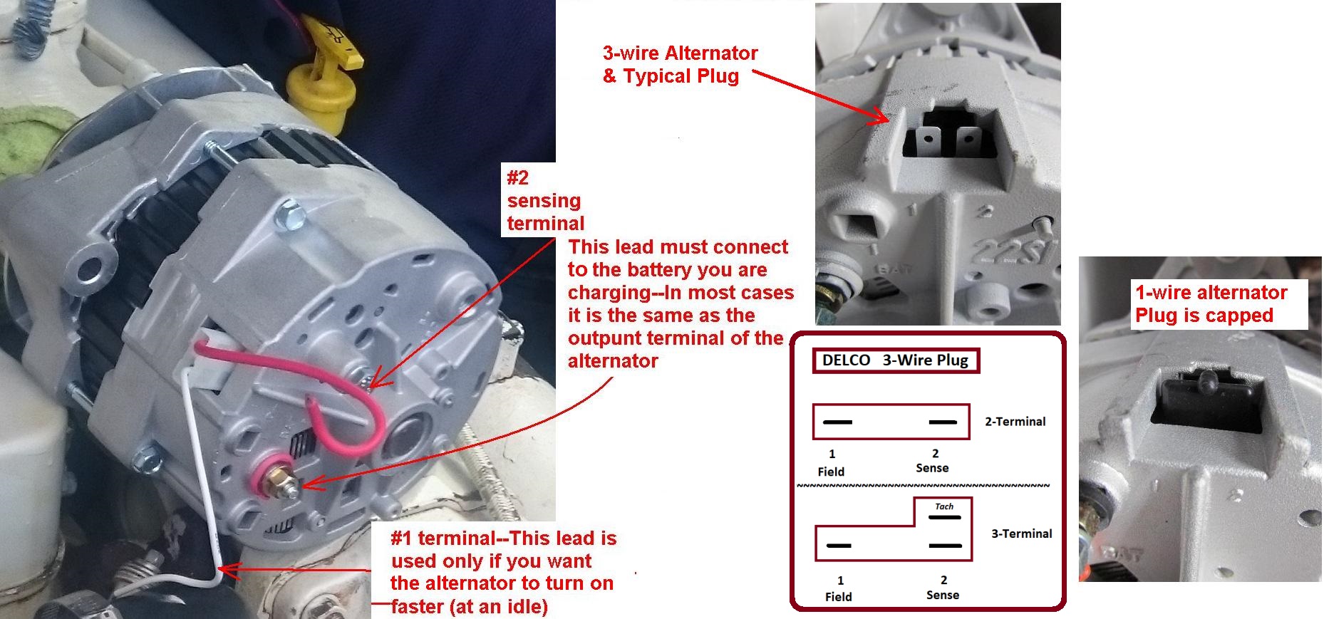
1 is for a sense wire and 2 is for a excite wire.
22si wiring diagram. Use a delco 21si or 22si plug connector as appropriate to adapt this single wire alternator for remote sense. Proceed with general battery isolator installation instructions 188012 page 2 group 1 or technical bulletin 2. With key on power is then transferred through the no charge indicator light to the 1 spade on the alternator regulator connection. Two blades labeled 1 and 2.
22si alternator wiring diagram wiring diagram is a simplified normal pictorial representation of an electrical circuit it shows the components of the circuit as simplified shapes and the capacity and signal connections in the company of the devices. This diagram shows the simple wiring diagram for negative ground delco si series alternators the ignition switch is most commonly powered from the starter battery stud but source may vary depending on application. Here is the official delco wire diagram for a one wire alt with gauge ground kept the ground wire to it to the cab and bolted the other two wires together. Delco 22si breakdown 2011 j n auto electric inc.
Nelectric co 1 800 366 7100 3 120 12041 1846900 kit output terminal 12 24 external 12 24 internal x 1 874 120 12042 10479702 kit output terminal m6 1 0 external 12 24 internal x 1 917 120 12044 1971673 kit relay terminal pin external 8 32 internal x 1 260 120 12048 1852519 kit relay terminal pin external 8 32 internal x 1 260. Connect a sense wire from the 2 terminal of the regulator to the 1 terminal of the battery isolator.

One Dollar Usb Sound Card Turned O Scope Cards One Dollar Usb


Imagen Relacionada Acondicionado Aire Acondicionado
22si Delco Alternator Wiring Diagram Kuiyt Fuse12 Klictravel Nl

No Enfria Arriba Ni Abajo Cambio De Tubo Capilar Video 1 8
