220v Single Phase Motor Wiring Diagram Ul Listed

240v Single Phase Motor Wiring Diagram Wiring Diagram And

Single Phase Forward Reverse Motor Wiring Diagram 1 With Images
220v Single Phase Motor Wiring Diagram Ul Listed Wiring Diagram

Wiring Diagram For 220 Volt Single Phase Motor With Images Ac

16 Stunning Wiring Diagram For 220 Volt Single Phase Motor

Wiring Diagram For 220 Volt Single Phase Motor With Images

In the above one phase motor wiring i first connect a 2 pole circuit breaker and after that i connect the supply to motor starter and then i do cont actor coil wiring with normally close push button switch and normally open push button switch and in last i do connection between capacitor.
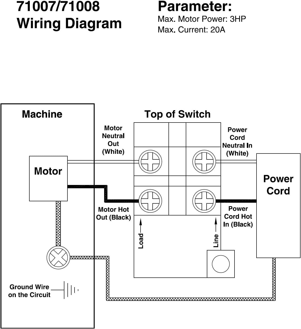
220v single phase motor wiring diagram ul listed. 1 3 1 hp qd relay 280 10 4915 sixth digit depends on hp. 1 2 1 hp crc qd relay 282 40 5015 sixth digit depends on hp. Each component ought to be placed and linked to different parts in particular manner. In this video jamie shows you how to read a wiring diagram and the basics of hooking up an electric air compressor motor.
A star delta is used for a cage motor designed to run normally on the delta connected stator winding. Just as in the three phase motor diagram the motor shows the power supply lines as being identified with the t. Schematic diagrams for the single phase motors. For most shore facility applications this is the case.
I have attached an image of the correct wiring diagram copied from your picture. Motor maintenance single phase motors and controls page 53 menu. Homeowners what is constant pressure. The control circuit may be operated manually or automatically when the control circuit is wired through sensors or other control devices.
The above diagram is a complete method of single phase motor wiring with circuit breaker and contactor. Ask question asked 5 years 1 month ago. Firstly the stator winding is connected in star an. These tips can be used on most electric motor brands such as weg baldor.
Single phase motor wiring diagram with capacitor baldor single phase motor wiring diagram with capacitor single phase fan motor wiring diagram with capacitor single phase motor connection diagram with capacitor every electrical arrangement is made up of various unique pieces. Single phase 220 volt ac motors are really two phase 240 volt motors especially when compared to three phase 208 volt motors and single phase 120 volt motors. Replacing a 220v single phase motor with a 220v split phase motor. In many cases the single phase motors on board a.
Correct wiring of 1 phase 220v electrical motor. The basic diagram view a shows a circle with two leads labeled t1 and t2. Electrical wiring for single phase motor controls tobi a motor control is simply a relay contactor that acts as a switch which is activated by a different power source or a control circuit. Ul listed fire protection.
This is because the motor s single phase actually operates on the difference between the two 120 volt phases that comprise the residential 240 volt input.

12 Complex Electric Motor Wiring Diagram Ideas With Images

Wiring Diagram For 220 Volt Single Phase Motor With Images

Wiring Diagram For 220 Volt Single Phase Motor With Images

Wiring Diagram For A Single Phase Motor 230 V Szliachta Org With

Wiring Diagram For 220 Volt Submersible Pump With Images

220v Single Phase Wiring Diagram 32 Wiring Diagram Wire Diagram

Wiring Diagram For 220 Volt Single Phase Motor Circuit Diagram

Single Phase Motor Wiring With Contactor Diagram With Images

16 Stunning Wiring Diagram For 220 Volt Single Phase Motor

Wiring Diagram For 220 Volt Single Phase Motor Car Audio Capacitor
Ce Approved Mc Single Phase Motor Wiring Diagram For Air

3 Phase 240v Motor Wiring Diagram With Images Electrical

Wiring Diagram For 220 Volt Single Phase Motor With Images
